
This problem is a coupled problem: As rockmass damage influences the hydraulic conductivity and as a consequence the resulting pwp-distributuion, which in turn affects the mechanical response. BE developed a framework to efficiently solve the hydro-mechanically coupled problems even for 3D, large-scale discontinuum models including high levels of complexity for both geometric resolution and mining activity sequence.
An important outcome of the coupled simulation is the evolution of new additional fluid flowpaths due to mining induced rock mass damage. This aspect needs to be considered carefully, as this in turn may adversely effect the pwp distribution and flux rates.
Hydrological model feature capabilities
- complex geometry and mining sequence
- hydraulic properties: isotropic, orthotropic, fully anisotropic
- hydraulic properties: rockmass damage dependent (increase in permeability with increase in rockmass damage, as function of equiv. dev. plast. strain)
- flow along and across discontinuity structures (faults, DFNs)
- transient or steady-state analyses
- solution dependent boundary conditions
Modelling examples
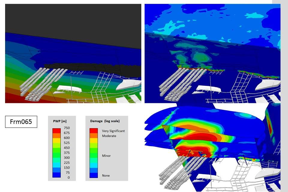
Figure 1: Coal mine, assessment of hydraulic interconnectivity between aquifers (top sedimentary layer and coal seam) across an aquitard. Clockwise from top left: pwp-distribution, rockmass damage, damage on bedding planes and faults.
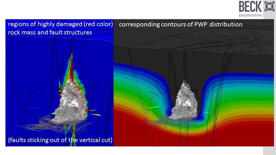
Figure 2: Utilization of the hydro-mechanical coupling framework to model increased flow through fragmentated rock within the cave region. The cave growth is modelled using another coupling of the mechanical response to a solid particle flow code.
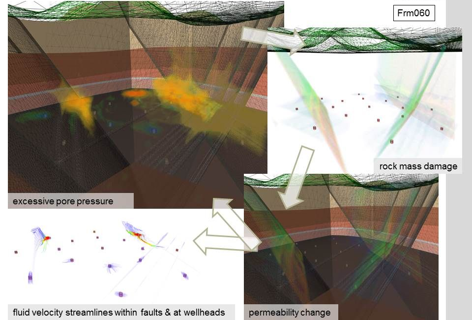
Figure 3: Utilization of the hydro-mechanical coupling framework to model increased flow through fragmentated rock within the cave region. The cave growth is modelled using another coupling of the mechanical response to a solid particle flow code. Clockwise from left: current state of cave shape, an equivalent rockmass damage distribution, resulting pwp-distribution.
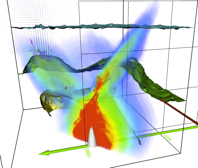
Figure 4: Interaction of the hydro-mechanical coupling framework for a production/injection well schedule within a reservoir: excessive pore pressure cloud, influencing the mechanical response (here: rockmass damage), leading to a change in hydraulic conductivity, affecting the fluid flow direction and magnitude as well as the pwp-distribution.
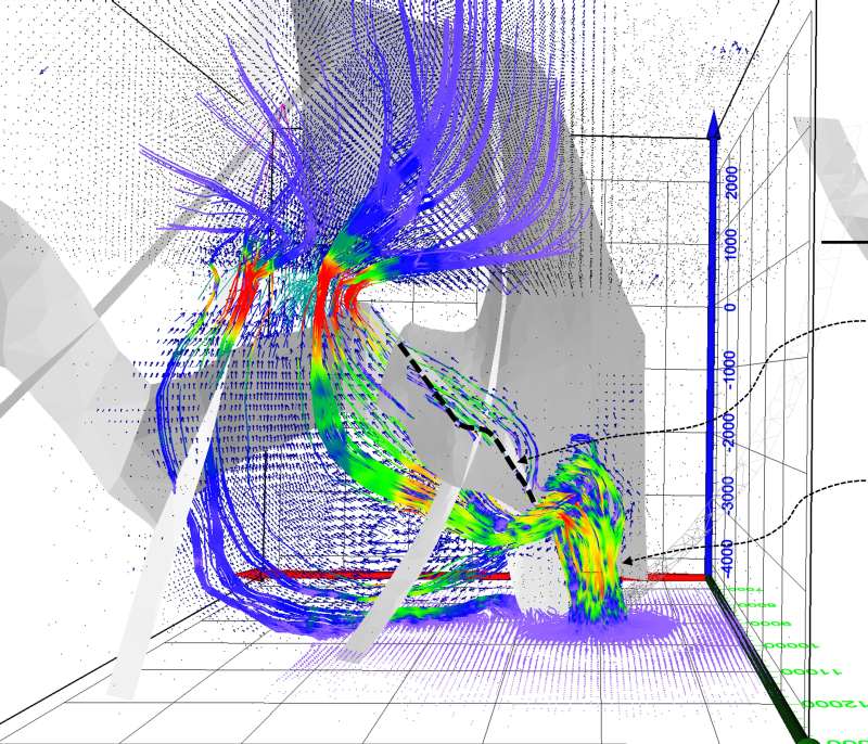
Figure 5: Development of additional fluid flowpaths due to evolution of rockmass damage. A cooling magma chamber (cupola shape) represented by an imposed fluid flux across the cupola surface. Left: Faults are excluding in this picture because of clear visibility. Countour cloud representing rockmass damage, vectors represent relative fluid velocities. Right: velocity streamlines showing the concentrated flow at confluence of major fault structures, and the spreading within the more permeable upper sedimentary domains.
Contact:
For further information, please contact Dr Arnd Flatten or info@beck.engineering.